The geometric parameters of the tool play a key role in machining and have a decisive impact on machining accuracy and efficiency. In the actual machining process, only through reasonable design and optimization of these parameters can high-efficiency and high-precision machining goals be achieved. Therefore, in-depth research and understanding of the specific meanings of the following eight categories of tool geometric parameters are of great significance for improving processing quality and effects.
These eight categories of tool geometric parameters include the tool’s edge angle, rake angle, relief angle, tool nose radius, edge angle, helix angle, cutting depth and feed rate, etc. The values and combinations of these parameters directly affect the cutting performance, cutting force, cutting heat, tool life, and machined surface quality of the tool.
The design and selection of tool geometric parameters directly affect processing performance and workpiece quality. The following are eight categories of tool geometry parameters and their typical applications.
1. Geometric parameters
1.1 Tool rake angle
Definition: The angle between the rake face of the tool and the plane perpendicular to the cutting direction.
Application: Positive rake angle: suitable for processing soft materials (such as aluminum, copper) and low-hardness materials, which can reduce cutting force and cutting heat.
Negative rake angle: suitable for processing hard materials (such as stainless steel, high-temperature alloys), providing higher tool strength and durability.
1.2 Tool relief angle
Definition: The angle between the tool flank and the cutting plane.
Application: Small relief angle: suitable for hard material processing and interrupted cutting, increasing tool durability.
Large relief angle: suitable for processing soft materials, reducing friction on the flank surface and improving surface quality.
1.3 Tool tip angle
Definition: The angle between the main cutting edge and the secondary cutting edge.
Application: Large tool tip angle: suitable for processing hard materials to improve tool strength and durability. Small tip angle: suitable for soft materials and finishing, improving surface quality.

1.4 Main declination angle
Definition: The angle between the main cutting edge and the feed direction of the workpieces.
Application: The main deflection angle affects the direction and magnitude of cutting force. Large entering angle: suitable for heavy cutting and chip breaking, reducing radial force. Small entering angle: suitable for finishing and improving surface quality.
1.5 Auxiliary declination angle
Definition: The angle between the minor cutting edge and the feed direction of the workpieces.
Application: The secondary deflection angle affects the surface finish of the workpiece and the durability of the tool. Main declination angle: suitable for processing with high precision and high surface quality requirements. Small secondary deflection angle: suitable for heavy cutting and rough machining.
1.6 Cutting edge arc radius
Definition: The arc radius of the cutting edge of the tool.
Application: Large cutting edge arc radius: suitable for heavy cutting and rough machining, improving tool strength and durability. Small cutting edge arc radius: suitable for finishing and thin-walled parts processing to improve surface quality.
1.7 Helix angle (for augers and milling cutters)
Definition: The angle between the spiral cutting edge and the tool axis.
Application: Large helix angle: suitable for soft materials and high-speed cutting, providing better chip removal performance. Small helix angle: suitable for hard materials and low-speed cutting, improving tool stability.
1.8 Cutting edge length
Definition: The length of the cutting part of the tool.
Application: Long cutting edge: suitable for deep cutting and large depth of cut processing to improve cutting efficiency. Short cutting edge: suitable for finishing and light cutting, providing better control and surface quality.

2.Parameter optimization
2.1 Material properties
Different materials require different tool geometry parameters. For example, soft materials (such as aluminum) can use larger rake angles and helix angles, while hard materials (such as titanium alloys) require smaller rake angles and smaller helix angles.
2.2 Processing type
The tool geometry parameters for roughing and finishing are significantly different. Roughing typically requires a larger edge radius and a stronger cutting edge, while finishing requires a smaller edge radius and a higher surface finish.
2.3 Cutting conditions
High-speed cutting and low-speed cutting have different requirements for tool parameters. High-speed cutting requires optimizing the tool rake angle and helix angle to reduce cutting heat and cutting force; low-speed cutting requires attention to the strength and durability of the tool.
3. Typical application examples

3.1 Automobile manufacturing
Optimization of rake and relief angles: Use positive rake angles and moderate relief angles to machine aluminum alloy engine parts to reduce cutting forces and improve surface quality. Selection of helix angle: Choose a milling cutter with a large helix angle to process aluminum body parts to improve chip removal efficiency.

3.2 Aerospace
Negative rake angle and large edge arc radius: used for processing titanium alloy and high-temperature alloy parts to ensure tool strength and durability. Adjustment of the main deflection angle: Small main deflection angles are used for finishing complex-shaped aero-engine parts to provide high surface quality.
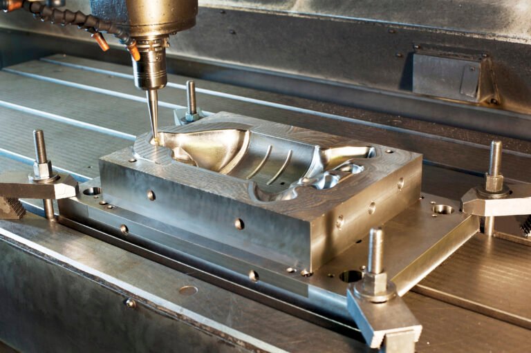
3.3 Mold manufacturing
Selection of tool tip angle: Large tool tip angle is used for rough machining of the mold cavity, and small tool tip angle is used for finishing the mold surface. Adjustment of cutting edge length: long cutting edge is used for deep cavity mold processing, and short cutting edge is used for fine mold surface treatment.
3.4 Electronic equipment
Small rake angle and small edge arc radius: used for processing metal housings of precision electronic components, providing high surface finish. Selection of secondary declination angle: The large secondary declination angle is used to process high-precision connector components to ensure dimensional accuracy.